
Studies in Mamluk Vaulting
By Ahmed Enab
This log contains some notes and resources relating to a experiment in parameterizing a style of Mamluk vaulting popularized in medieval Cairo.

I advise you to research the basic components and terminology related to arch and vault construction before reading this log. The entries in the “Dictionary of Architecture and Building Construction” are very sufficient, and a lot of diagrams explaining these basic terms and components are available online.
Resources
For resources concerning stone cutting and general vault stereometry, I recommend these references:
Dwight Porter – Notes on Stereotomy
J. Chaix – Cours de Construction .06 : Traité de Coupe des Pierres
Émile Lejeune – Traité pratique de la Coupe des Pierres
For resources concerning the construction of vaults in the Mamluk era, refer to the works of orientalist such as Jules Bourgoin, Julius Franz, Wilfred Joseph Daly and the contemporary Doris Behrens-Abouseif.
The book I used the most was an Arabic translation for a book – probably – named “Arabic Architecture in Egypt”, attributed to Wilfred Joseph Daly, and I can not find any traces of the original book or its author, so if you can please contact me; anyway, the book title in Arabic is “العمارة العربية بمصر”, it’s very much available in Egypt, and I found a lot of scanned copies of it on the internet, but I am not sure of their copy right status.
Also, the following sites contain a lot of books on the subject, with no copyright restrictions, just search for the right keywords or the name of the author:
Gallica – Bibliothèque nationale de France
Process
I tried to use a modeling technique close to the construction method used by ancient artisans to construct cross (groin) vaults, which is mentioned in the book by Dwight Porter. I adapted it to suit the more complex geometry of Mamluk vaults, and it goes as follows:

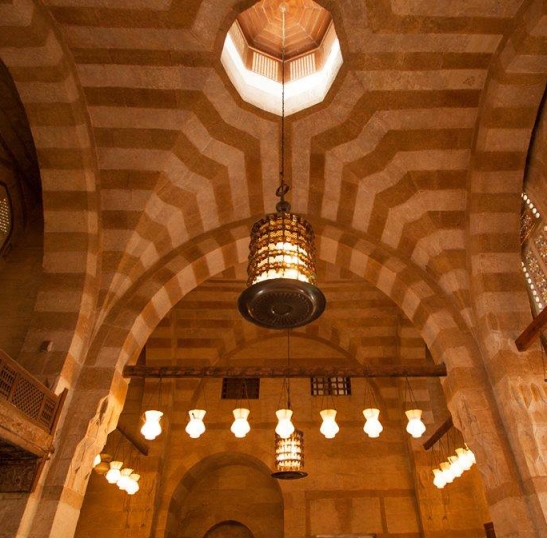
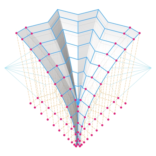
We start from a projection plan of the groins or the arris of the vault. The lines drawn here in light green are those of fillers, not of any arris lines.

An arch profile is drawn on one of the outer edges of the vault bay. In most cases, these vaults have a 4-fold symmetry, so it won’t matter which edge, but in general, the profile should be drawn on the most visible side of the bay. Note that I’ve used a simple one centered arc, with a radius equal to 2/3 of the span; but of course any profile curve could be used.
The arc is divided, and these division points mark the number of tiers in the vault, as well as the number of voussoirs of the outer arches. Note that the last segment of these divisions has a length equal to 1/2 the length of the prior segments, in a manner that would give us a key stone with a total full length for its intrados and extrados edges.

These division points are then projected to the ground plane; as I’ve said, I tried to follow a modelling process close to that of the traditional construction technique. I’ve actually tried other methods, but this one seemed the most comprehensible and straight forward.
These division points are then translated to the projection of the vault’s arris lines. Drawn by hand the designer or artisan would have probably used parallel lines to locate these points, I mean parallel to the lines connecting the ends of the arris projection lines, which are coincidentally marking the fillers in our case. I’ve made use of the “parameter space” feature in “Grasshopper” to do the job, meaning that the relative coordinates of the projected points on the first line are used to locate the corresponding points on each of the arris projection lines. Come to think of it, this whole process in basically stretching the profile curve we’ve drawn in the second step to match the lengths of the various arris projection lines.

Now, the points are given an elevation equal to that of the division points which they were derived from in the first place, and of course these points define all the vault arris curves. This method of projection, translation, then giving elevation to the construction points ensures that all the upper and lower voussoir edges are parallel in both plan and section, and after some experimentation with other construction and division methods I came to the conclusion that this produces the most appealing visual results.

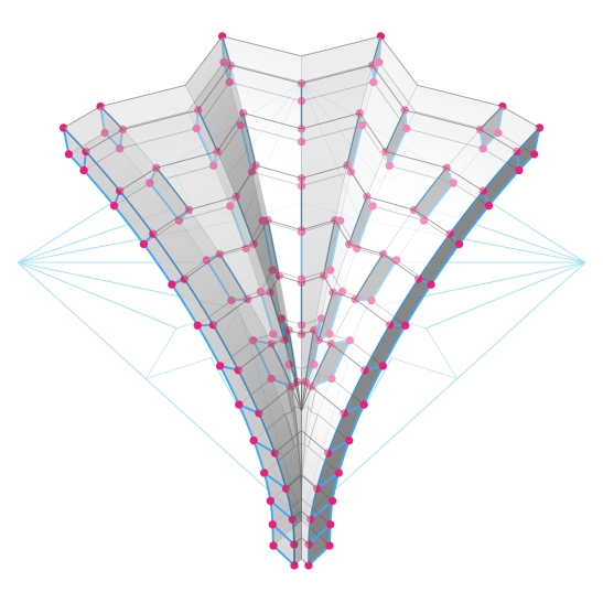
From these curves the surfaces composing the intrados could be created.

And in the tradition of all masonry construction, these surfaces are grouped so that the vertical joints between the voussoirs are alternated.
Now, before discussing the extrados surfaces, I would like to point out that ancient builders probably didn’t give these surfaces much consideration, and if they did they would have wasted much time, since these surfaces are almost never visible to the building users.

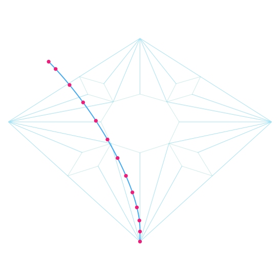
But since we live in a different age, with a different perception of structures, and even have different methods of obtaining our knowledge of these structures; for example I don’t think ancient builders learned about vaults from diagrams like this, or even conceived them in that way:

So, I decided to give some attention to the geometry of the vault’s extrados surfaces, and parametrize the whole thing as if it was a stand alone structure that could be perceived from both the inside and the outside alike.

Now, starting from the original profile curve, we create a base profile for the extrados surfaces, the curve is created by an offset of the original curve with a value equal to the desired voussoir thickness.
The same process of division, projection, translation, then giving height is carried out to construct the curves of the extrados. Note the intersection of the curves over the bay’s corner point.

The extrados surfaces are created.

And, altering the vertical joints is taken in account. And, you must have noticed that these surfaces are created using only the extrados curve segments above their intersection point.
Now, exterior arches are added to vault, and by exterior I mean that they extend beyond the span of the vault, of course this is a necessity, since vaults are constructed of stones or bricks that have a physical thickness, but I am pointing this out because even without this physical necessity, these arches add visually to the vault, and without them the mass of the vault looks amputated, unstable, and unpleasant. In historical construction these arches would have been buried inside the abutments or walls enclosing the vault, and they would have formed an interlocking between the voussoirs of the vault and the wall courses.

Of course, arch surfaces are added to the intrados surfaces as well.
Now, the remaining voussoir surfaces are created, here, the vertical ones.

And, the horizontal ones.

And, voilà, this side is done.

Al-Ablaq is a method of alternating rows of different colored stone, which was used a lot in the rendering of these vaults.

I think this method really brings out and clarifies the geometry of this type of vaulting.

And since this particular vault has a 4-fold symmetry, its just a matter of mirroring/rotating this 1/4 to get the full vault.
Fruits of Parameterization
As you might know, the best thing about working with “grasshopper” or parameterized modelling in general, is that if you’ve done something once, you can do it again and again with out much change to the core definition of your geometry. By a change of parameters like the arris lines of the vault, its profile, or numerical values like the number of voussoirs, or their thickness, you can easily reach variants on the principal concept. Here are a few examples showing variations on the basic definition of Mamluk vaults:
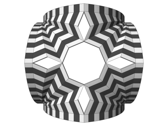

This is the same vault used in the description of the modelling process, which is based on a simple 4-fold octagonal design for its plan.


Similar; based also on an octagonal 4-fold design for the its plan, but it is apparent that the arris lines are more complex.


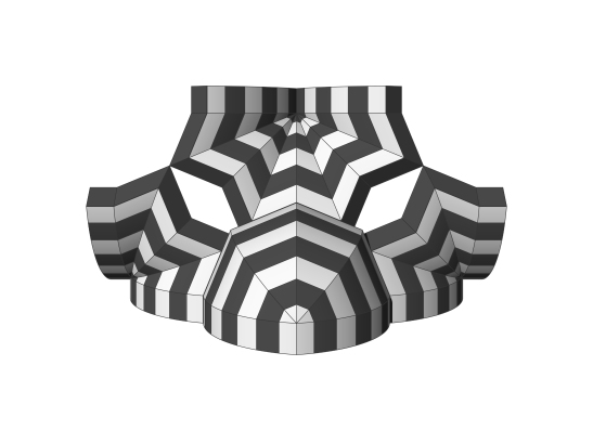
This is an example has a 2-fold symmetry. Note the distinct pendant-like formation in the back of this category of vault designs. Also, the plan of this particular vault features a hexagonal filler at its front which influences the whole design of the arris lines plan.
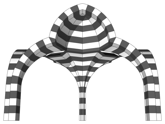
This vault has a number of distinct features, first the whole profile of the vault could be perceived as a trilobed arch. We could also divide this vault into two distinct parts, a lower one which is similar to all the examples we’ve discussed here, and an upper one which could be seen as a 4-sided half dome. Note also that though this vault has only a 2-fold symmetry, the geometry of its arris lines plan is derived from octagonal 4-fold construction lines.

This last example has a trilobed profile, and its plan is very much similar to that of the second example, with minor variations on the shape of the fillers; the sides of the center cross are not parallel basically.
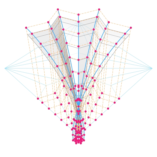
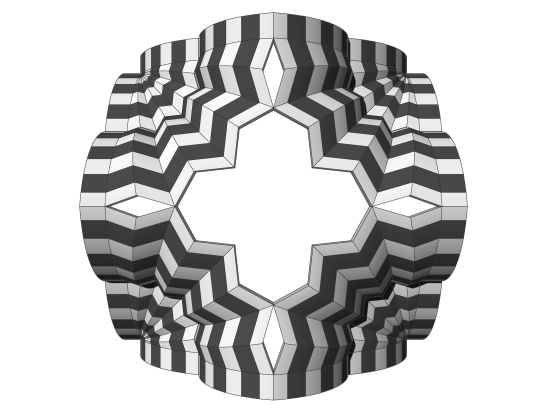
Finally, even the individual voussoir geometry of these vaults turned out to have a crystalline character that really mesmerized me since I discovered it.
I am sharing these last two diagrams through my Instagram account, if you want to follow my future work. And thank you.
